A Comparison of three amplifier circuits of transistors
In an electronic circuit, the object of amplification is variation, and the essence of amplification is to control and convert the energy of the DC power supply through active elements (transistors or field effect transistors) under the action of input signal, so that the energy of the output signal obtained by the load from the power source is much larger than that provided by the signal source to the amplifier circuit. Transistor amplifier circuits can be divided into common emitter amplifier circuits, common collector amplifier circuits and common-base amplifier circuits. While field effect transistors can be divided into common source amplifier circuit and common drain amplifier circuit, which are corresponding to common-emitter amplifier circuits and common collector amplifier circuits of transistors.
The three basic amplifier circuits of transistors are compared through the following three main performance indicators (magnification times A, input resistance Ri, and output resistance Ro).
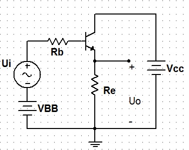
Common emitter amplifier circuit:

Alternating current:

Micro change equivalent circuit:
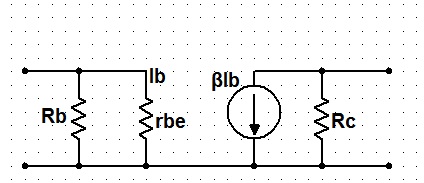
Magnification times: A=Uo/Ui=-βRc/rbe;
Input resistance: Ri=Rb//rbe;
Input resistance: Ro=Rc;
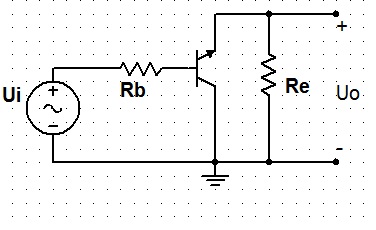
Common collector amplifier circuit:
alternating current path:
Micro change equivalent circuit:
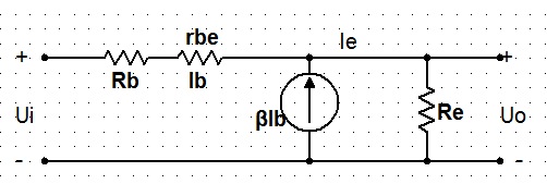
Magnification times: A=Uo/Ui=IeRe/[Ib(Rb+rbe)+(1+β)IbRe];
Input resistance: Ri=Ui/Ii=Ui/Ib=[Ib(Rb+rbe)+IeRe]/Ib=Rb+rbe+(1+β)Re;
Output resistance: Ro=Re//[(Rb+rbe)/(1+β)];
Common base amplifier circuit:
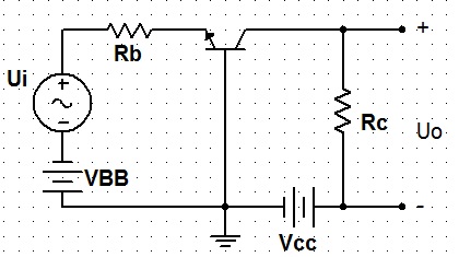
alternating current path:

Micro change equivalent circuit:
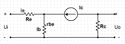
Magnification times: A=Uo/Ui=Ic*Rc/(Ie*Re+Ib*rbe)=βRc/[rbe+(1+β)Re];
Input resistance: Ri=Ui/Ii=Ui/Ie=(Ie*Re+Ib*rbe)/Ie=Re+rbe/(1+β);
Output resistance: Ro=Rc.
The Comparison of three amplification circuits:
A common emitter amplifier circuit can amplify both current and voltage, and the input and output resistances are among the middle place of the three kinds of circuits. The frequency band is narrow. It is commonly used as the unit circuit of a low-frequency voltage amplifier circuit.
A common collector amplifier circuit can only amplify current but voltage. It has the largest input resistance and the smallest output resistance in the three circuits. It has the characteristics of voltage following and is often used in the input and output stages of voltage amplifier circuits.
A common base amplifier circuit can only amplify voltage but current, and the output resistance is small. The magnification times of voltage and output resistance are equivalent to those of the common emitter amplifier circuit, which is with the best high frequency characteristics in the three amplifier circuits. It is often used as a broadband amplifier circuit.
For more information about transistors, please visit this website: http://www.apogeeweb.net/article/72.html
